
High -Flow Throttle Body
Pictures and details of what I did to mine
The throttle body modifications that I made to Dakota are very simple, anyone with a little mechanical ability can do it. If you decide to work with your original throttle body, this modification will give you the most horsepower for your dollar. If you don't feel confident doing it yourself, you can have a machine shop do the work for you. Don't get me wrong, it takes about five hours to to everything and you will get covered with aluminum dust. In the end, it was worth it! the performance gains were incredible! The stock engine is very restricted by the throttle body, a modified engine begs for even more air.
Below is a List of the changes I made:
1. The bore was opened to 50mm all the way to the top.
2. The bore separators were thinned and smoothed.
3. The stock air cleaner attatching plate and bolt were removed.
4. An S-shaped air cleaner threaded shaft was installed.
5. The throttle blades were thinned on the front and back edges.
6. The throttle shaft was thinned to about 50% of stock.
7. Counter-sunk allen-head screws were installed in the throttle shaft.
The first thing you should do is to get together everything that you'll need for the job.
Tools:
1. Dremel tool or an air die grinder
2. 5/16 socket (to remove the bracket)
3. T-20 Torx driver (to remove the blades)
4. T-25 Torx driver (to remove the sensors)
5. An awl (to remove the throttle stop plug)
If you want to keep your stock throttle body, you can get a new one for about $220 or about $100 for a used one. I chose to order a new one from Koller Dodge in Chicago.
You'll also need:
1. One new t-body to manifold gasket
2. One bottle of Loctite, medium strength
3. One can of Gunk Throttle Body Cleaner
DON'T FORGET TO WEAR YOUR SAFETY GLASSES FOR THESE FOLLOWING REASONS:
1. GRINDING PRODUCES FINE, HOT METAL PARTICLES THAT CAN BURN YOUR EYES!
2. WIRE WHEELS FREQUENTLY EJECT WIRES, I HAD SEVERAL STICK INTO ME!
3. IT IS NOT WORTH LOSING YOUR VISION TO GAIN A FEW HORSEPOWER!
Well, let's get started!
1. Side View
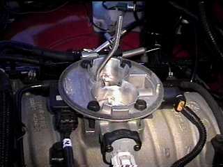
DISASSEMBLY
After you have removed the throttle body from the engine, the first order of business is to disassemble it. Remove the Throttle Position Sensor(TPS) and the Idle Air Control Motor(IAC) with a T-25 driver. Remove the 5/16 bolts that hold down the throttle bracket. Pay attention! . First, mark both blades with a permanent marker or a scribe. Make sure you label which way is up and which is one is left and right, don't forget to mark front and back also. Draw a circle with a permanent marker around the throttle blades on the bore so that you have a reference point from where the blades rest. Now its time to remove the throttle blades frome the shaft. Remove the screws with a T-20 Torx driver and open the throttle so that you can pull the blades out from the bottom. Finally you can remove the shaft by pulling it out smoothly.
2. Front View
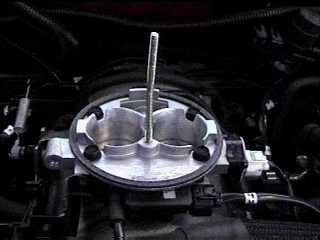
PORTING AND POLISHING
Here comes the dirty work. You should now be able to see the marks you made with the marker use these as a guide, try not to grind away anything below the line. You are on your own for the next few hours now. Do your best to even the bore out, start by grinding down from the ridge first and working your way toward the top. I used a 220 grit roll for the initial grinding. There is another way to do the same job, but it requires the use of a drill press and a sanding attatchment. Start by setting the stop on the press at the lowest point you want to grind and then locking it down in that position. There is an even easier way, take it to a machine shop.
I used the original blades as a reference guage for when I had removed enough material. I also thinned and smoothed the bore separators and gave them a knife edge to redice turbulence. After I was satisfied that I removed enough metal, I decided to go over it with 220 grit sandig rolls to polish the bores. I also opened it up a bit more by removing material from the top edges of the bore to make sure that there was a smooth transition. I followed this by hand sanding with 400 grit sandpaper and finishing with 600 grit when I was satisfied that all the scratches were gone. As a final step, I used a wire polishing wheel to shine up the bores.
3. Close-up
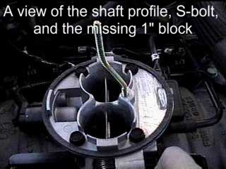
QUIET PLEASE!
A small but effective mod is to completely remove the 1" tall locating block at the front of the throttle body. Rmoving this actually quited the "wooshing" noise while accelerating part throttle and also reduced a little turbulence when using an open element air cleaner.
4. Bore with blades open
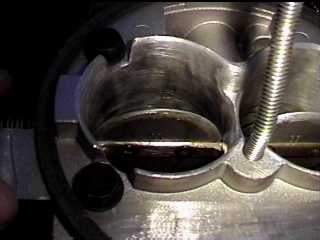
THE SHAFT
The goal is to grind the screw head side (bottom) of the shaft down to 1.5mm and the thread side (top) down to 2.5mm. It is important to leave more on the thread side so that the screws have some thread to grab.
The stock butterfly shaft is 10mm thick which is about 20% of the bore diameter, about twice as thick as it needs to be. My solution grind away enough material to reuce the thickness to 5.5mm. I bet you're gonna ask, "Is that going to be strong enough?" Yes, it's made out of steel! The stock shaft is a perfect example of over-enginering. They could have easily made it 1/3 of it's actual thickness, if you don't belive me, just look at a Holley carb.
The thickness of the blade is 1.5mm and will not be thinned for a few reasons. The first is that the slot in the shaft is 1.5mm wide, thinning the blade will leave a gap. The second reason is that the blade is made out of aluminum and may bend or flex if thinned too much. The third and final reason is that the blade is thinner than the shaft anyway and does not provide a restriction to the air flow. I did grind the backside of each blade to produce a knife edge so that turbulence would not be an issue.
Another problem are the screws that attach the blades to the shaft. The stock screws are rather large torx-headed screws that actually stick out into the airstream on both sides. The solution is to install countersunk torx screws and cut the threads flush with the shaft.
This is the fun part. Examine the shaft closely, you will see that one side is threaded and the other has recesses in it for the screws. If you did as I said, you can see the marks that you made on the shaft earlier. These marks are your stopping point when grinding. There are bearings holding each side of the shaft, it is very important that you don't grind where the bearing are. Besides holding the shaft, they also seal the shaft. You should also leave about 3mm in the center untouched so that the shaft can be supported in the center.
After you are aware of the marks, its time to start grinding. I started by grinding away closest to the marks and worked my way inward. I concentrated on the bottom (screw head) side first, grinding to 1.5mm, and then moved to the bottom (thread) side and ground down to 2.5mm. I did one side at a time to minimize any screw-ups. After you are finished grinding, test fit the shaft to the throttle body. Touch up if necessary. Now polish the shaft with a finer grit and then with a wire wheel. Countersink the screw head side of the shaft so that the heads sit flush with the shaft when screwed in.
Once the shaft is re-installed in the throttle body, attach the blades and cut the excess threads of the screws flush with the shaft. Remove the screws and reinstall with red (medium) Loctite. Make sure that the blades are aligned so that they are closed at rest.
5. Bore with blades closed
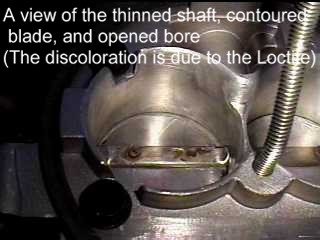
Now that you have more airflow, its possible you may need to correct a fast idle condition. If you have not been careful and removed a little too much metal, the idle-set screw may need to be acessed. To do this you need to pull out the plug. Don't worry, the plug is quite thin and its not as tough as it looks. Lightly tap an awl into the side of the plug and pull it out. You'll need to readjust the idle to 650 rpm once you get the throttle body back on the manifold.
Now, just reinstall all the sensors and bolt it back on. In sure hope you remembered to get that extra t-body to manifold gasket. Finally, bend a replacement air cleaner stud to an S-shape as shown in the picture. The easiest method is is to first screw the stud into the t-body and then bend it to shape by hand. I used a replacement Mr. Gasket carb stud kit to get the bolt.
After you are done, go for a drive to make sure everything works. Don't beat on it yet, you are getting more airflow now, so there is a possibility of running too lean until the computer learns the new airflow and fuel requirements. I have found that it takes about 3 days to get the computer to re-adjust, 4 to 5 days for the full effect.
OTHER MODS YET TO BE DONE
1. I have not done it yet, but I plan to remove the ridges (air-horns) at the top of the bores. I will cut the ridges flush and radious the edges, I've been told this is worth about 30 cfm improvement.
2. I also plan to machine out the bores to either 52mm or 55mm and fit it with some Holley blades.
3. I plan to add some countersunk or rounded allen bolts to replace the stock bolts once the air-horns are removed.
I will keep you updated as I make changes.
Click here to go to Mark's '99 Dakota Home Page
 flyboy01@worldnet.att.net
 Back to the DML Home Page
- Back to the Maintenance, Modifications & Upgrades Section
Back to the DML Home Page
- Back to the Maintenance, Modifications & Upgrades Section
